This professional troubleshooting manual focuses on the 13 most frequent malfunctions of spiritore CNC plasma cutters in industrial metal cutting operations, offering systematic cause analysis, practical troubleshooting steps and targeted repair solutions to help operators quickly resolve equipment failures and restore stable production.
What Is a CNC Plasma Cutter & Its Working Principle
A spiritore CNC plasma cutter is an integrated intelligent processing equipment that combines a high-precision CNC control system with a professional plasma cutting unit. Equipped with a user-friendly and stable CNC operating system, the machine ionizes high-speed compressed airflow through high-temperature nozzle excitation to form conductive plasma medium. When electric current passes through the ionized airflow, a high-temperature concentrated plasma arc is generated. The intense heat of the plasma arc locally melts and vaporizes the metal material at the workpiece cutting edge, while the high-velocity plasma airflow blasts away molten metal to form smooth, precise cutting seams. Adopting advanced annular airflow stabilization technology, the equipment produces elongated, stable plasma arcs, enabling efficient, cost-effective cutting of all conductive metal materials for industrial processing.
Common CNC Plasma Cutter Faults & Basic Solution Guidelines
In daily industrial cutting production, spiritore CNC plasma cutters may encounter various operational faults due to improper operation, parameter mismatch, component aging and environmental interference. When failures occur, operators should remain calm, accurately judge fault symptoms, locate root causes step by step, and implement standardized troubleshooting and repair measures.
1. Excessively Low Working Air Pressure
If the operating air pressure of the plasma cutter is far below the factory-specified standard value, the plasma arc ejection speed will decrease significantly, with insufficient air supply failing to form high-energy, high-speed plasma arcs. This directly leads to poor cutting seam quality, incomplete material penetration and slag accumulation on cutting edges.
Main causes: Insufficient air supply from the air compressor, low pressure setting of the equipment air regulating valve, oil contamination and blockage of the solenoid valve, and unobstructed air pipeline. Operators need to inspect the above components one by one and rectify abnormalities in a timely manner.
2. Excessively High Working Air Pressure
Overly high input air pressure will disperse the concentrated plasma arc column after arc formation, scatter arc energy and reduce cutting penetration and strength.
Main causes: Improper manual adjustment of input air parameters, excessive pressure setting of the air filter pressure reducing valve, or functional failure of the pressure reducing valve assembly.
3. Improper Installation of Nozzle & Electrode Wearing Parts
The core wearing parts including electrodes and nozzles adopt threaded installation structures and require complete tightening and standardized assembly. Incomplete thread fastening and incorrect installation of the swirl ring will cause unstable plasma arc operation, fluctuating cutting quality and accelerated wear and damage of core consumables.
4. Low Input AC Voltage
Before equipment commissioning and formal operation, it is necessary to verify the load capacity of the grid power supply and check whether the power cord specifications meet equipment operating standards. The spiritore CNC plasma cutter must be installed away from high-power electrical equipment and strong electromagnetic interference environments to avoid low AC voltage caused by power supply instability, which affects cutting performance.
5. Poor Ground Wire & Workpiece Contact
Reliable grounding is a mandatory pre-operation preparation for plasma cutting. Failure to use professional grounding tools, insulating oxide layers on workpiece surfaces, and severe aging and damage of grounding wires will result in poor conductive contact between the ground wire and workpiece, triggering unstable cutting and arc failure.
6. Unreasonable Cutting Speed & Torch Verticality Deviation
The cutting speed and operating current must be matched according to different metal materials and plate thicknesses. Either excessively fast or slow cutting speed will cause uneven cutting surfaces and residual upper and lower edge slag. Meanwhile, if the cutting torch is not perpendicular to the workpiece surface, the plasma arc will spray obliquely, resulting in inclined cutting seams and unqualified processing accuracy.
Detailed Troubleshooting Table (Faults, Causes & Solutions)
| Fault Phenomenon | Root Causes | Troubleshooting Solutions |
|---|---|---|
| Host power indicator off after turning on main power switch | 1. Power | 1. Replace damaged indicator |
| Power indicator on, but cooling fan not rotating after three-phase power startup | 1. Three-phase power | 1. Troubleshoot three-phase |
| Power indicator and fan work normally, no air flow from torch nozzle after activating test gas switch | 1. No compressed air input | 1. Overhaul air supply equipment and uncl |
| No air injection and host program response after closing cut switch and torch switch (test gas function normal) | 1. Torch switch or | 1. Overhaul or replace torch switch |
| No cutting arc generated despite normal nozzle air flow after turning on torch switch | 1. Three-phase power phase | 1. Eliminate three-phase power phase loss fault |
| Contact cutting normal, non-contact cutting no arc ignition | 1. 15A fuse blown | 1. Replace blown |
| Partial gear failure of cutting thickness selection switch | 1. Thickness adjustment switch or | 1. Replace |
| Unstable plasma arc during cutting operation | 1. Abnormal air pressure (too high | 1. Readjust air |
| Failure to reach rated cutting thickness | 1. Input three-phase voltage lower than standard 38 | 1. Adjust input voltage to standard |
| Cutting workpiece dimensional deviation & offset | 1. Damaged nozzle | 1. |
| Excessively wide cutting seam & poor incision quality | 1. Overly | 1. Optimize |
| Burning damage of plasma cutting torch | 1. Uncompressed metal pressure cap after consumable replacement | 1. Fasten pressure cap immediately after replacing nozzle and |
| Frequent burnout of rectifier diodes D1-D6 | 1. Low reverse withstand | 1. Select diodes with reverse withstand voltage above 1 |
Daily Operation Cautions for CNC Plasma Cutters
Unstandardized operation and neglected daily details are the main causes of unstable cutting quality and frequent consumable replacement for spiritore CNC plasma cutters. The following standardized usage tips can effectively extend equipment service life and stabilize processing quality:
- Start Cutting From Workpiece EdgesPrioritize edge starting cutting instead of direct piercing cutting whenever possible. Align the torch nozzle with the workpiece edge to ignite the plasma arc, which can effectively reduce consumable loss and prolong the service life of nozzles and electrodes.
- Shorten Unnecessary Pilot Arc TimeNozzles and electrodes wear rapidly during arc ignition. Place the torch close to the cutting metal area before activating the arc to minimize idle pilot arc time and reduce unnecessary component wear.
- Avoid Nozzle Overload OperationLong-term overload operation will cause rapid nozzle failure. The actual operating current should be controlled at 95% of the nozzle’s rated current (e.g., set 100A nozzle working current to 95A) to ensure stable operation and avoid overload damage.
- Adopt Standard Cutting DistanceOperate in strict accordance with the cutting distance specified in the equipment manual. For piercing processing, adopt twice the normal cutting distance or the maximum plasma arc transmission height to ensure complete piercing and stable cutting.
- Control Piercing Thickness Within Machine AllowanceDo not process steel plates exceeding the machine’s rated piercing thickness. The maximum safe piercing thickness is generally 50% of the standard cutting thickness to avoid arc instability and equipment damage.
- Keep Torch and Consumables CleanDirt and impurities on the torch and wearing parts will seriously affect plasma arc performance. Place consumables on clean flannel during replacement, and regularly clean electrode contact surfaces and nozzles with hydrogen peroxide cleaning agents to maintain cutting precision.
10 Frequently Asked Questions About CNC Plasma Cutters
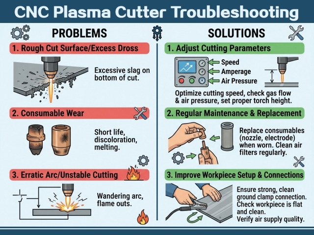
Q1: Why does excessive dross form on the bottom edge of cut workpieces?
Bottom edge dross is mainly caused by unreasonable cutting travel speed. Slow cutting speed produces soft easy-to-polish dross, while excessive speed forms hard stubborn dross. Adjust the cutting speed in 10% increments according to the official equipment cutting parameter chart to eliminate dross.
Q2: What causes sudden arc loss during cutting?
Intermittent arc extinction is mostly triggered by insufficient air pressure, poor workpiece grounding contact or oxidized contaminated workpiece surfaces. Ensure the grounding clamp is tightly connected to bare clean metal and maintain stable and continuous air supply for the equipment.
Q3: How to prevent thin sheet metal from cutting deformation?
Adopt the minimum current that can realize full material penetration, increase cutting travel speed appropriately, and optimize cutting sequence to reserve cooling time for adjacent cutting paths. Equipping a plasma water table can significantly reduce deformation of thin sheets below 16 gauge.
Q4: Why are cut holes tapered and out-of-round?
For holes smaller than 1 inch, lock the THC at the factory-recommended cutting height and reduce the cutting speed to 60% of the conventional perimeter cutting speed. This enables the arc trailing edge to fully cut the material and form standard cylindrical holes.
Q5: What is the replacement cycle for plasma consumables?
Replace nozzles and electrodes in time when you find enlarged nozzle apertures, electrode crater wear, wandering plasma arc or increased cutting dross. Timely replacement of genuine consumables is the most effective way to solve most cutting failures. Form a fixed maintenance schedule to track component wear.
Q6: What causes inconsistent bevel angles on cutting edges?
Worn or damaged nozzle apertures will disrupt plasma arc symmetry and lead to uneven cutting bevels. Keep the cutting height within ±0.010 inch error, and check the tight installation of swirl rings and shield caps to ensure consistent cutting precision.
Q7: Does compressed air moisture affect cutting quality?
Yes. Excessive moisture in compressed air will destroy the internal ionization environment of the torch, cause arc instability and accelerate consumable wear. It is recommended to install a refrigerated air dryer and coalescing filter at the equipment air inlet to dry air.
Q8: Why does THC drive the torch to collide with the workpiece at corners?
During corner deceleration, the arc voltage changes abnormally, causing THC system misjudgment of standoff distance. Disable the THC automatic adjustment function during equipment deceleration according to the official manual to avoid torch diving collision.
Q9: Can handheld plasma torches be used on CNC cutting tables?
Handheld torches with notched nozzles are prone to blockage and failure in mechanized CNC cutting. Only professional flat-face machine torches are applicable to CNC plasma cutting equipment.
Q10: What is the budget for a small-shop CNC plasma cutting system?
Entry-level 4×4 small cutting tables cost about $5,000–$8,000, while industrial production-grade systems are priced at $15,000–$50,000 and above. The overall budget needs to reserve funds for consumable replacement and professional CAM software.