Operating a spiritore CNC router for woodworking, metal fabrication and other industrial processing tasks often comes with unexpected technical glitches. Even high-quality spiritore CNC router units tend to develop functional issues after long hours of continuous operation, incorrect parameter configuration or improper manual operation. If you are frequently plagued by various machine malfunctions and struggle to find targeted fixes, this comprehensive guide will walk you through the 22 most prevalent CNC router faults, paired with practical troubleshooting methods and effective solutions to restore normal production quickly.
From axis movement failures and spindle abnormalities to carving errors and system alarms, we cover all typical operational problems of spiritore CNC routers. Keep reading to master systematic fault diagnosis skills and daily operation guidelines.
Common CNC Router Faults & Detailed Troubleshooting Solutions
Problem 1: Single-axis or Three-axis Stagnation & Irregular Movement
Solutions
1. Loose connection or internal functional damage of the motion control card.
2. Performance failure of the drive module corresponding to the faulty axis.
3. Operational malfunction of the matching stepper motor for the axis.
4. Cracked or loose shaft coupling, which usually leads to displaced engraved patterns and distorted fonts.
5. Worn, damaged lead screw or faulty screw nut assembly affecting axis movement.
6. Abnormal sliding and fast movement failure of the movable axis.
7. Mismatched parameters between drive subdivision, operating current and software system configuration.
Problem 2: Z-axis Out-of-Control (Tool Collision Failure)
Solutions
1. Loose installation or functional breakdown of the equipment control card.
2. Static electricity interference disrupting internal signal transmission.
3. Damaged circuit wiring of the Z-axis servo/stepper motor.
4. Incorrect setting or corrupted files of the processing path program.
5. Electromagnetic signal interference generated by the frequency converter.
6. System bugs or virus infection on the connected operating computer.
7. Insufficient power output of the Z-axis motor and loose coupling accessories.
8. Undersized Z-axis drive current or wrong wiring of signal transmission lines.
Problem 3: CNC Router System Error Alerts
Solutions
1. Poor connection or hardware damage of the control card.
2. Abnormal operation and functional failure of the drive module.
3. Operational faults of the equipment stepper motor.
4. Signal disorder caused by static electricity interference.
5. Broken or short-circuited motor power lines.
6. Poor transmission or damage of data signal lines.
7. Wrong programming and parameter setting of processing paths.
8. Broken or loosely installed shaft coupling components.
9. Excessively fast processing speed and overlarge curve acceleration parameters in system settings.
10. Computer system crashes, bugs or virus attacks.
Problem 4: Uneven Engraving Depth & Inconsistent Pattern Shading
Solutions
1. Loose connection or functional failure of the control card.
2. Performance degradation or complete failure of the stepper motor.
3. Drive module faults and inconsistent current/subdivision parameters with software settings.
4. Circuit failure and poor contact of the Z-axis motor.
5. Abnormal operating status of the spindle motor.
6. Frequency converter electromagnetic interference and incorrect data parameter configuration.
7. Static electricity interference affecting equipment signal stability.
8. System loopholes or virus infection on the control computer.
9. Unflat and deformed working platform leading to uneven processing.
Problem 5: Irregular & Distorted Routing Patterns
Solutions
1. Functional damage and operational failure of the control card.
2. Strong electromagnetic interference from the frequency converter.
3. Incorrect or corrupted processing path files imported to the system.
4. Signal distortion caused by static electricity accumulation.
5. Unreasonable parameter settings in the CNC control software.
6. Drive module faults or mismatched drive current and subdivision parameters.
7. Damaged and poorly connected data transmission lines.
8. Computer system malfunctions or virus intrusion.
Solutions
1. Non-vertical installation between spindle and worktable, resulting in inconsistent milling depth.
2. Worn, damaged or unqualified routing bits with poor cutting performance.
3. Abnormal operation and functional faults of the control card.
4. Malfunctions of Z-axis drive module and damaged lead screw assembly.
Problem 7: Sudden Spindle Stop During Operation
Solutions
1. Internal short circuit fault of the spindle motor coil.
2. Current shielding failure and internal signal disorder.
3. Incorrect frequency converter parameters or hardware failure.
4. Structural damage and functional failure of the control card.
5. Short circuit of spindle power lines and data transmission lines.
Problem 8: Abnormal Operating Noise of Spindle Motor
Solutions
1. Improper parameter debugging of the frequency converter.
2. Spindle stalling and failure to operate normally.
3. Internal hardware damage of the spindle, mainly including bearing wear and fracture.
Problem 9: Reverse Movement of Machine Axis & Opposite Direction Reset
Solutions
1. Modify and correct parameter settings of program files via Notepad.
2. Adjust and rewire the internal circuit of the frequency converter.
3. Reset the motor operating direction in the CNC control software.
Problem 10: Failed Automatic Origin Reset
Solutions
1. Wrong setting of axis moving direction.
2. Poor connection or hardware failure of the control card.
3. Damaged limit switch or faulty data transmission lines.
4. Functional failure of the drive module.
5. Performance degradation and operational faults of the stepper motor.
Problem 11: Random Startup & Unexpected Stop of Spindle
Solutions
1. Functional damage of the equipment control card.
2. Operational malfunctions of the frequency converter.
Problem 12: Software Launch Failure with "Operation Failed" Prompt
Solutions
1. Reinstall the control card driver or replace the PCI slot for the control card hardware.
2. Reinstall dual data lines and inspect for broken pin faults.
3. Replace the damaged and ineffective control card.
Problem 13: Software Initialization Error 4 & Three-axis Alarm Prompt
Solutions
1. Inspect and reconnect the two data lines between computer and CNC equipment.
2. Replace the blown fuse on the control box adapter board.
3. Verify the 85V power supply system operates stably and normally.
Problem 14: Routing Pattern Dislocation & Dimensional Deviation
Solutions
1. Inspect and correct errors in CNC processing path files.
2. Fasten loose fixing screws of lead screw and optical rod gaps.
3. Calibrate and standardize all software operating parameters.
Problem 15: Z-axis Tool Lifting Failure During X-axis Movement (Reverse Lifting Action)
Solutions
1. Inspect the operating status, power output and drive current of Z-axis stepper motor to eliminate motor faults.
2. Troubleshoot poor contact and intermittent circuit faults of Z-axis motor wiring.
3. Repair or replace the faulty control card.
Problem 16: Spindle Motor Stalling & Reverse Rotation Fault
Solutions
1. Reset and recalibrate the frequency converter operating parameters.
2. Reverse the wiring connection of frequency converter signal lines.
Problem 17: Axis Closed Alarm After Software Startup
Solutions
1. Troubleshoot drive module faults or poor contact of computer output signal lines.
2. Fasten loose and poorly connected motor power lines.
Problem 18: Automatic Limit Trigger During Processing Operation
Solutions
1. Check whether the designed processing path exceeds the machine’s effective working stroke range.
2. Reset and optimize the software limit parameter configuration.
Problem 19: Software Startup Failure & Deformed Processed Workpieces
Solutions
1. Reinstall the operating system and CNC control software on the computer.
2. Fasten loose fixing parts of X/Y-axis lead screws.
3. Replace worn, aging and unqualified routing bits.
Problem 20: Spindle Slow Operation & Sudden Stop During Processing
Solutions
1. Install a professional voltage stabilizer to solve voltage instability and equipment overload issues.
2. Inspect and re-weld loose or disconnected intermediate circuit wiring.
Problem 21: Uncertain Forward & Right Offset During Origin Calibration
Solutions
1. Replace faulty limit switches with unstable closing and bouncing signals.
2. Re-fasten loose wires of the drive circuit system.
Problem 22: Uncertain X/Y/Z Axis Position After Machine Reset
Solutions
1. Replace permanently closed and damaged limit switches.
2. Repair or replace faulty drive lines (X-axis 14&15 pin short circuit, Y-axis 13&15 pin short circuit, Z-axis 31&15 pin short circuit).
3. Replace the damaged driver board module.
Operation Safety Cautions
1. Avoid equipment installation during thunderstorm weather, do not set power sockets in humid environments, and never touch uninsulated power cords to prevent electric shock.
2. All operators must complete professional pre-job training, strictly abide by standardized operating procedures, and prioritize personal and equipment safety during all operations.
3. The equipment’s rated working voltage is 210V-230V. For environments with unstable voltage or high-power electrical equipment, install a professional voltage stabilizer under technical guidance.
4. Ensure reliable grounding of the machine body and control cabinet; never plug or unplug data lines when the equipment is powered on.
5. Operators are forbidden to wear gloves during processing; wearing protective goggles is strongly recommended for safety protection.
6. The machine gantry adopts aviation aluminum and steel composite structure with soft texture. Do not apply excessive force when tightening fixing screws (especially drive motor screws) to avoid thread slipping and damage.
7. Firmly clamp routing bits before operation and keep tools sharp. Dull cutters will reduce processing quality and cause motor overload damage.
8. Keep fingers away from the tool working area. Do not disassemble the spindle arbitrarily or process materials containing asbestos.
9. Do not exceed the machine’s maximum processing stroke. Cut off the total power supply for long-term shutdown, and conduct machine debugging only under professional guidance.
10. In case of equipment abnormalities, refer to the official troubleshooting manual or contact suppliers for professional maintenance to avoid artificial secondary damage.
Standard CNC Router Assembly Steps
Important Warning: All assembly operations must be performed in a fully power-off state.
1. Complete the mechanical docking and connection between the machine body and control cabinet.
2. Connect the data transmission lines between the machine body and control box.
3. Insert the machine power cord into a standard 220V power socket.
4. Connect the control box and computer: insert one end of the data cable into the control box signal interface and the other end into the computer port.
5. Connect the control box power cord to a standard 220V power supply.
6. Tool installation: Fit a matched collet into the spindle taper hole, insert the routing bit into the collet, fix the spindle neck with a small wrench to prevent rotation, and tighten the spindle nut counterclockwise with a large wrench to firmly clamp the tool.
Standard CNC Router Operation Process
1. Complete typesetting and design according to actual processing requirements, accurately calculate processing paths, and save different tool paths as independent files.
2. Preview and verify the accuracy of processing paths, then import qualified path files into the CNC control system.
3. Fix processing materials stably, set the processing origin, start the spindle motor, and calibrate the spindle speed reasonably.
4. Power on the equipment and enter standby working mode.
Boot Self-Check Procedure
1. Turn on the power switch, the equipment indicator light will illuminate. The machine automatically completes reset and self-check, with X, Y, Z axes returning to zero and moving to the initial standby position.
2. Adjust the three axes via the handheld controller to align with the processing origin, select matched spindle speed and feed speed, and finish pre-processing preparation.
Engraving & Routing Processing
1. Edit and confirm all parameters of cutting and processing files.
2. Transmit the verified files to CNC equipment, and the machine will automatically complete cutting and engraving operations.
Processing Completion Operation
After the processing task is completed, the machine will automatically lift the tool and return to the top of the processing starting point.
Daily Equipment Maintenance Specifications
1. The daily continuous working duration of the equipment shall not exceed 10 hours. Keep cooling water clean and ensure the water pump operates normally to prevent water shortage of the water-cooled spindle. Replace cooling water regularly to avoid spindle overheating; replace cooling water with antifreeze in low-temperature winter environments.
2. Clean platform dust and transmission system debris after each use. Lubricate X, Y, Z three-axis transmission parts weekly: apply lubricating oil to polished rods and high-speed butter to lead screws. In cold winter, clean lead screws and guide rails with gasoline first before oiling to avoid excessive transmission resistance and processing dislocation.
3. All electrical maintenance and inspection work must be carried out after complete power cutoff, confirmed by the extinguished monitor screen and main power indicator.
Key Operation Remarks
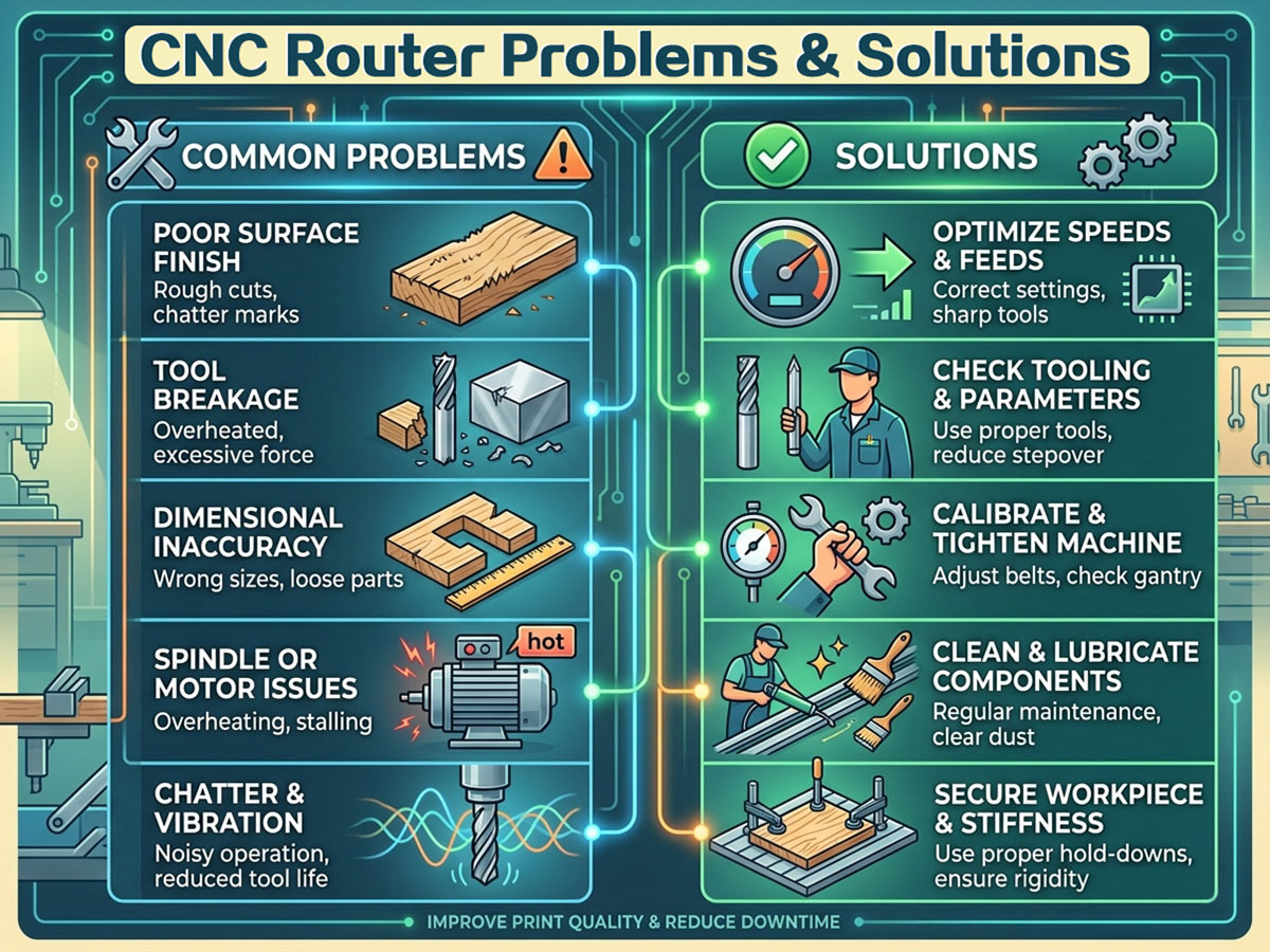
spiritore CNC routers are high-precision automated processing tools widely used in woodworking, metalworking and multiple industrial manufacturing fields. However, improper daily maintenance, unreasonable parameter setting and mismatched processing materials easily cause common faults including poor cutting quality, severe tool wear, mechanical vibration, dimensional inaccuracy and electrical failures.
Timely fault diagnosis and regular maintenance can effectively extend equipment service life and avoid secondary mechanical damage. It is recommended to develop standardized daily maintenance habits and select matched tools and processing parameters according to different materials to ensure long-term stable and efficient production.